

Diagnosis and Test Tool Procedures
The OTIS LCB-2 board plays an important role in elevator control and fault monitoring. When an elevator stops operating normally, the LED indicators on the LCB-2 board and diagnostic information from the Test Tool (TT) can help maintenance technicians identify abnormal conditions and narrow down potential causes.
This guide explains the preliminary checks, normal LED indicator conditions, troubleshooting methods, and Test Tool diagnostic procedures for the OTIS LCB-2 board. It covers important monitoring points such as the safety circuit, door contacts, brake circuit, remote serial communication, and elevator leveling signals.
1. Preliminary Checks Before Troubleshooting the OTIS LCB-2 Board
Before checking individual components, several preliminary procedures should be completed.
1.1 Main Power Switch
Switching off the main power will delete all stored fault data.
Before disconnecting the power supply, use the Test Tool (TT) to analyze and record the existing fault information. This helps prevent important diagnostic records from being lost.
1.2 Switching from Inspection Mode to Normal Operation
When returning the elevator from inspection mode to normal operation, follow this sequence:
1. Switch the elevator to inspection mode.
2. Open the landing door.
3. Press the emergency stop switch in the car-top inspection box.
4. On the car top, close the landing door.
If the sequence is incorrect, the equipment may not return to normal operation.
The following indications may appear:
- · The INS LED on the LCB-2 board flashes.
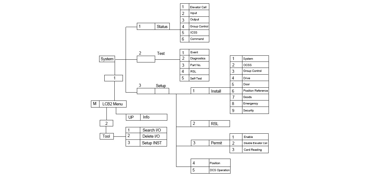
- · The Test Tool status menu (M-1-1-1) displays the flashing message: TCI-LOCK!
Check the switching sequence before proceeding with further troubleshooting.
1.3 Important Notes About the 8LS Limit Switch
The operating status of the 8LS limit switch can be monitored through the Test Tool status menu (M-1-1-1). The status information is displayed on the top line:

If the elevator car slightly settles for any reason and causes the 8LS cam switch to lose power, the 8LS switch will reset.
According to the original troubleshooting reference, after 15 minutes, the elevator will be taken out of service and automatically travel to the bottom floor, where it will remain stopped.
After the 8LS switch resets and the normal operating sequence is restored:
- If the elevator is still at the top of the shaft, manually lower the car until the 8LS switch loses power.
- Switch the ERO box from ERO back to normal operation.
If the elevator does not immediately return to service, continue troubleshooting according to the following LED inspection procedures.
2. OTIS LCB-2 Board LED Indicators and Normal Status
The LED indicators on the LCB-2 board provide important information about the operating condition of the elevator control system.
The following table summarizes the normal LED conditions described in the original reference.
|
LED |
Function |
Normal Status |
| MP | Motor thermal protection (MPD) | OFF |
| BC | Brake current monitoring | OFF |
| VCL | LCB-2 board voltage check | ON |
| GRP/J | Group control / relay | OFF for single elevator; ON for group control |
| NOR/D | Normal operating mode | ON |
| ISN | Inspection mode | OFF |
| ES | Emergency stop | OFF |
| DOB | Door reopening | OFF |
| RSL | Remote serial communication check | Flashing |
| DW | Landing door contact | ON when door is closed; OFF when open |
| DFC | Car door fully closed contact | ON when door is closed; OFF when open |
| DOL | Door open limit | OFF when door is closed; ON when open |
| LV | Leveling zone detection | ON when the elevator is in the leveling zone; OFF when outside |
If an LED does not match its expected status, inspect the corresponding circuit and components.
3. OTIS LCB-2 Board LED Troubleshooting
3.1 MP LED Is ON
The MP LED indicates motor thermal protection status.
Check:
- Wiring between the LCB-2 board and the brake switch, referring to the electrical diagram.
- Whether the motor PTC thermistor has been activated.
3.2 BC LED Is ON
The BC LED monitors brake current.
Check:
- Wiring between the brake and the control cabinet.
- The F3 (1A) fuse on the main transformer.
- The input and output voltages of rectifier RF1 on the main transformer, using a multimeter and the electrical diagram.
3.3 VCL LED Is OFF
Check:
- The F1 (4A) fuse on the LCB-2 board.
- The power supply between the LCB-2 board and connector P8.
3.4 GRP/J LED Is Flashing
Before performing the following operations, switch off the main power supply.
Check:
1. Interchange the phase sequence at connector P9 (380V AC) on the LCB-2 board.
2. Switch on the main power and check the GRP/J LED again.
3. If the LED status remains unchanged, switch off the main power and repeat the procedure using another phase combination.
3.5 NOR/D LED Is OFF
Check:
- Input and output voltages on the LCB-2 board.
- The operation board self-test procedure (refer to C-12 in the original manual).
3.6 ISN LED Is ON or Flashing
Check:
- The remote station inside the COP, address 16, connector 31, pin 1.
- Use the TT RSL test and verify Adr-16 Bit=3 IN-OFF.
- Wiring of the ERO box switch and TCI box switch.
3.7 ES LED Is ON
The ES LED indicates the emergency stop circuit status.
Check:
- TES, PES, and SCS switches.
- The F1 (1A) fuse on the transformer.
- Safety circuit wiring.
- The 8LS safety contact.
- Whether relay RV is energized and contact 43143 is closed.
3.8 DW LED Shows an Abnormal Status
If DW is OFF when the landing door is closed or ON when the door is open, check:
- Landing door switch operation.
- Landing door switch wiring.
3.9 DFC LED Shows an Abnormal Status
If DFC is OFF when the car door is closed or ON when it is open, check:
- Car door switch operation.
- Car door switch wiring.
3.10 DOL LED Shows an Abnormal Status
If DOL is OFF when the door is open or ON when the door is closed, check:
- The car door.
- Door open limit switch contacts.
- If the elevator does not have front and rear doors, verify the RDOL I/O list: IO 554 > AD=01, P=0.
3.11 DOB LED Is ON
Check:
- Whether the door photoelectric sensor is operating normally.
- SGS and SGL switch contacts.
- DOB button and remote station.
3.12 LV LED Shows an Abnormal Status
If LV is OFF when the elevator is in the leveling zone or ON when it is outside the leveling zone, check:
- Pulse switches 1LV and 2LV.
- Relays LVI and LV2.
- Associated wiring connections.
3.13 RSL LED Is OFF or ON Continuously
The RSL LED monitors remote serial communication.
Check the remote serial communication wiring and associated connections.
3.14 Resetting the LED Status After Troubleshooting
After resolving the fault, reset the LED status to obtain the correct indications.
Operate the switch on the ERO box:
1. Switch to ERO.
2. Switch back to Normal.
Then check the LED indicators again.
If the LED status is still abnormal after these checks, continue with Test Tool diagnostics.
4. OTIS LCB-2 Board Troubleshooting Using the Test Tool (TT)
The Test Tool provides additional diagnostic information when the LED indicators alone cannot identify the problem.
The following procedures are listed in the original troubleshooting manual.
4.1 Check the Elevator Operating Status
Connect the Test Tool and enter:
M-1-1-1
Use the status menu to check the current elevator operating condition.
If the fault cannot be identified, continue with the following diagnostic procedures.
4.2 Analyze Previously Stored Events
Enter:
M-1-2-1
Review the previously stored EVENTS to identify relevant fault information.
Important: The original manual states that fault data is deleted whenever the main power is switched off. Therefore, analyze and record the event information before disconnecting the power supply.
4.3 Run the Self-Test
Enter:
M-1-2-5
Execute the SELFTEST procedure.
If the problem remains unidentified, continue with the remote station test.
4.4 Check Remote Station Communication
Enter:
M-1-2-4
Run the RS2-Test to verify the correct operation of the remote station associated with the fault.
4.5 Check Input Status
Enter:
M-1-1-2
Review the INPUTS status to identify abnormal input signals.
4.6 Check Output Status
Enter:
M-1-1-3
Review the OUTPUTS status to inspect the output conditions of the control system.
Conclusion
Troubleshooting an OTIS LCB-2 board requires a systematic inspection of LED indicators, safety circuits, door contacts, brake monitoring, power supplies, and communication signals.
Start by recording existing fault information, checking the normal LED conditions, and inspecting the corresponding circuits. If the cause remains unclear, use the Test Tool to review EVENTS, perform SELFTEST, check remote station communication, and verify input and output signals.
For maintenance work, always refer to the applicable OTIS electrical diagrams and service documentation. Electrical testing and safety circuit inspections should only be performed by qualified elevator technicians.
Post time: Nov-20-2026