Understanding the symbols and component codes used in an escalator control cabinet is essential for efficient troubleshooting, routine maintenance, and electrical inspections. Each code on a wiring diagram represents a specific electrical component, switch, relay, or safety device within the escalator control system.
This reference guide provides the English meanings of common Sigma escalator control cabinet schematic symbols, helping maintenance engineers quickly interpret electrical drawings and improve service efficiency.
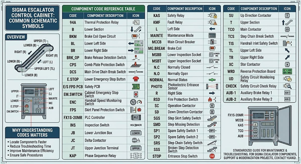
Sigma Escalator Control Cabinet Component Code Reference
|
Code |
Component |
Code |
Component |
| 94A | Thermal Protection Relay | N.C | Normally Closed |
| B | Lower Section | N.O | Normally Open |
| BKM | Brake Coil Open Circuit | NORMAL | Normal Status |
| BL | Lower Left Side | ||
| BR | Lower Right Side | PHOTO | Photoelectric Entrance Sensor |
| BRK_OP | Brake Release Detection Switch | R | Right Side |
| CPS | Comb Plate Protection Switch | RSD | Fire Protection Switch |
| DCS | Main Drive Chain Break Switch | SC | Operation Contactor |
| E.STOP | Lower Emergency Stop Button | SD | Down Direction Contactor |
| E/S FPD PCB | Safety PCB | SGS | Step Skirt Safety Switch |
| EM.SWITCH | Control Cabinet Emergency Stop Switch | SMD | Step Missing Detection |
| ENC | Handrail Speed Monitoring Switch | SP1 | Spare Safety Switch 1 |
| FPS | Skirt Panel Protection Switch | SP2 | Spare Safety Switch 2 |
| FX1S-20MR | PLC Controller | SRS | Step Chain Safety Switch |
| INS | Inspection Switch | SSS | Broken Step Detection Switch |
| JB | Lower Junction Box | STOP | Entrance Stop Switch |
| JC | Delta Contactor | SU | Up Direction Contactor |
| JT | Upper Junction Terminal | T | Upper Section |
| KAP | Phase Sequence Relay | TCO | Main Contactor |
| KAS | Safety Relay | TCS | Step Chain Break Detection Switch |
| KMF | Fault Relay | TIS | Handrail Inlet Safety Switch |
| L | Left Side | TL | Upper Left Side |
| MAINTE | Maintenance Mode | TR | Upper Right Side |
| MCCB | Main Circuit Breaker | XC | Star Contactor |
| MG.BREAK | Brake Coil | WRD | Reverse Protection Board |
| MSBB | Lower Inspection Socket | UD | Safety Circuit Monitoring Relay |
| MSBT | Upper Inspection Socket | CHECK | Safety Circuit Check Relay |
| AUB-1 | Auxiliary Brake Relay 1 | AUB-2 | Auxiliary Brake Relay 2 |
Why Understanding Schematic Codes Matters
Electrical schematic diagrams are one of the most important references during escalator maintenance. Correctly identifying component codes allows technicians to:
- · Locate electrical components more quickly
- · Reduce troubleshooting time
- · Improve maintenance efficiency
- · Minimize equipment downtime
- · Ensure safe maintenance procedures
Whether performing preventive maintenance or diagnosing electrical faults, a clear understanding of schematic symbols helps engineers work more accurately and efficiently.
Typical Components Found in a Sigma Escalator Control Cabinet
The control cabinet integrates numerous electrical and safety devices, including:
- · PLC controller
- · Main and auxiliary contactors
- · Safety relays
- · Brake control components
- · Handrail monitoring devices
- · Step chain protection switches
- · Comb plate safety switches
- · Emergency stop circuits
- · Safety circuit monitoring relays
- · Inspection switches
Together, these components ensure reliable operation while continuously monitoring the escalator’s safety systems.
A standardized understanding of Sigma escalator control cabinet symbols is essential for maintenance personnel, electricians, and field engineers. Familiarity with these component codes can significantly improve troubleshooting efficiency, reduce maintenance time, and support safer escalator operation.
Looking for Sigma escalator spare parts, electrical components, or modernization solutions? YuanQi supplies high-quality escalator parts and provides professional technical support for maintenance and repair projects worldwide.
WhatsApp: 8618192988423
E-mail: yqwebsite@eastelevator.cn
Post time: Jul-03-2026