Before debugging the escalator, it must be confirmed that the distance between the two main driving wheel speed sensors and the main driving wheel teeth is 2mm-3mm, and the center distance between the two main driving wheel speed sensors should be guaranteed to be 40±1mm. When the main drive wheel rotates, the speed sensor can sense and generate speed pulses, and at the same time, the sensor probe will not be damaged by the main drive wheel. During the actual installation process, it is necessary to ensure that there is no oil on the sensor surface to avoid affecting the sensor's detection accuracy.
The main drive sensor installation diagram is shown below.
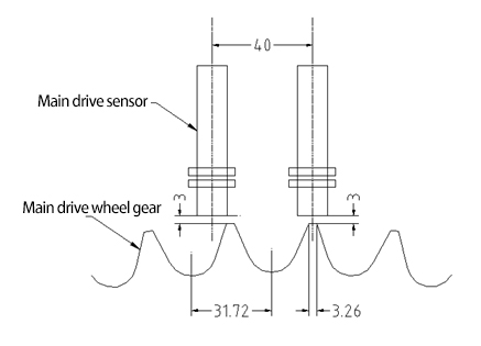
Main drive sensor installation dimensions
After the main drive sensor is installed, during the maintenance operation before self-learning, the pulses of the two main drive sensors can be monitored through the M2-1-1-5 menu interface, and the ladders with normal speeds of 0.5m/s and 0.65m/S, The feedback speed pulse is between 14 and 25HZ, and the normal phase angle of the AB phase is between 70° and 110°. If the phase angle between the speed pulse and the AB phase is not within the range, and the difference between the uplink and downlink phase angles is greater than 30°, please Adjust the sensor installation position. Refer to Figure 5 for theoretical requirements. When the escalator runs at a speed of 0.5m/s, the main drive value in the server monitoring interface is displayed as follows:
The actual display values of SPD1 (main drive speed sensor 1) and SPD2 (main drive speed sensor 2) will change according to the different parameters of the entire elevator.
Debugging before normal operation of escalator
Self-study Function Description:
In the new standard IECB, the MSCB multi-function safety control board adds a self-learning function for SP, MSD, HRS, and PSD. Through self-learning, the values of SP, MSD, HRS, and PSD can be obtained as a basis for fault judgment. After pressing M2-1-5 to enter the password, press M2-1-4 to enter the self-learning interface. After entering the self-learning interface, press the confirm key to enter the self-learning state. The self-learning function of MSCB multi-function safety control panel includes the following points:
1. The escalator cannot operate normally before self-learning is completed. The escalator can only succeed in self-learning when it is inspected and moved up under the power frequency state.
2. After starting the self-learning function, there will be a 10S stabilization time for the escalator status, and the escalator’s operating status will not be detected within 10S. The self-learning state can only be entered after 10 seconds of power frequency maintenance. After the self-learning is completed, the escalator will stop running, and then the escalator can operate normally.
3. After the self-learning is completed, the self-learning value will be compared with the benchmark value within the program to determine whether the self-learning value is correct.
4. The self-learning time is 30S-60S. If the self-learning is not completed after 60S, it is judged that the self-learning has timed out, that is, the self-learning failed.
5. The speed abnormality before the start of self-learning cannot be judged during the self-learning process. It can only be judged after the self-learning is completed.
6. Speed anomalies during the self-learning process can be determined within 5 seconds, the escalator stops running urgently, and the safety circuit relay SC on the MSCB multi-function safety control board is disconnected.
7. Self-learning adds a requirement for the phase difference between SP1 and SP2, which requires that the phase difference between SP1 and SP2 must be between 45°~135°.
Self-learning operation process:
| Steps | Server display | ||
| 1 | Pull out the short wires of terminals 601 and 602 on the bottom rail of the control cabinet | ||
| 2 | Set the IECB to power frequency operation state | ||
| 3 | Press M2-1-5. Enter the password menu | Password:9999 | Enter Password |
| 4 | Press M2-1-2-2 to enter the factory reset interface | Resume factory Press Enter... |
|
| 6 | Press SHIFTKEY+ENTER to restore factory settings | Affirm Resume Press Enter... |
|
| 7 | Press SHIFTKEY+ENTER to restore factory settings | Resume Factory Success! | |
| 8 | Press M2-2-5 to enter the password menu | Password:9999 | Enter Password |
| 9 | Press M2-2-2-2 to enter the factory reset interface | Resume factory Press Enter... |
|
| 10 | Press SHIFT KEY+ENTER to restore factory settings | Affirm Resume Press Enter... |
|
| 11 | Press SHIFT KEY+ENTER to restore factory settings | Resume Factory Success! | |
| 12 | Press M2-1-2-1 to enter the parameter setting interface | ||
| 13 | Set escalator speed step SPF | Set according to actual ladder type | |
| 14 | Set step width step width | Set according to actual ladder type | |
| 15 | Insert the service plug | ||
| 16 | Press M2-1-4 to enter the self-learning interface | Para. Learning Press<ENTER> |
|
| 17 | Press SHIFT KEY+ENTER to enter self-learning state | Start esc up by Inspection Box | |
| 18 | Start the maintenance uplink and continue to run until the self-learning success or failure is prompted. | See Table 3 for self-learning failure faults. Restart self-learning after troubleshooting. If the self-learning is successful or fails, please set the IECB to the frequency conversion state. | |
Table 7. Troubleshooting for failed self-learning. If self-learning fails, please troubleshoot according to the fault code displayed on the server. For detailed troubleshooting, please refer to Table 7. After troubleshooting, you need to re-self-learn.
| Serial number | Abnormal state | Server failure display | Troubleshooting |
| 1 | Abnormal state The SP value is not within the range of 14-25HZ | SPF | Check the step speed SPF and step width in M2-1-2-1, and check whether the SP1 and SP2 sensor installation meets the requirements |
| 2 | The phase difference between AB phases (SP1 is A phase, SP2 is B phase) is not between45°-135° | SPF | Check whether the installation of SP1 and SP2 sensors meets the requirements |
| 3 | MSD1 upper rung missing | B25 | Check whether the upper step sensor is installed correctly |
| 4 | MSD2 lower rung missing | B25 | Check whether the step sensor is installed correctly |
| 5 | The deviation between HDR and HL values exceeds 10% or the pulse mutation occurs during the self-learning process | B9 | Check whether the right armrest sensor is installed correctly |
| 6 | The deviation between HL and HR values exceeds 10% or the pulse mutation occurs during the self-learning process | B8 | Check whether the left armrest sensor is installed correctly |
8.3 Self-test after CHK self-learning is completed
After self-learning is completed, insert the non-maintenance plug, use the key switch to start the escalator normally, and perform self-test operation of the escalator. During the self-check operation, the escalator will run continuously for 2 minutes. During these 2 minutes, the self-start function will be temporarily disabled, and all fault protections of the escalator will be checked. If no fault is found during the self-check, it will automatically return to normal operation. No need Restart the escalator; if a fault is found, the escalator will stop running and display the corresponding fault. Common faults can be found on the inner wall of the control cabinet door. After troubleshooting, you need to re-self-check. The key switch box will display CHK for each self-check.
Every time it enters the normal state from the maintenance state, the escalator will enter the self-inspection state. During the self-inspection process, the key switch box will CHK first and the traffic flow light will go out.
Post time: Oct-24-2023