The KONE KDL16 V3F16ES inverter is an important part of the elevator drive system, responsible for controlling motor speed, torque, acceleration, and braking performance. By converting and controlling electrical power, the inverter ensures smooth elevator operation, accurate leveling, and comfortable passenger experience.
Understanding the internal structure and working principle of the V3F16ES drive helps maintenance engineers diagnose faults and improve repair efficiency.
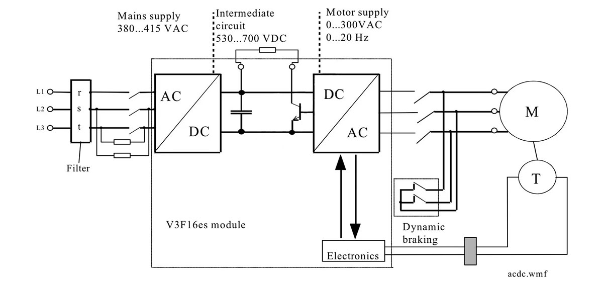
Working Principle of KONE V3F16ES Drive
The V3F16ES inverter works by controlling the power supply delivered to the elevator motor.
The main process includes:
1. Power input and conversion
The incoming AC power is processed through the main circuit system and converted into a suitable DC voltage.
1. DC intermediate circuit control
The intermediate circuit stabilizes the DC voltage through capacitors and related components, providing a stable power source for the inverter section.
1. Motor drive control
The inverter converts DC power into adjustable frequency AC output, controlling motor speed and torque according to elevator operation requirements.
Through precise control of acceleration, deceleration, and braking, the system achieves smooth elevator movement.
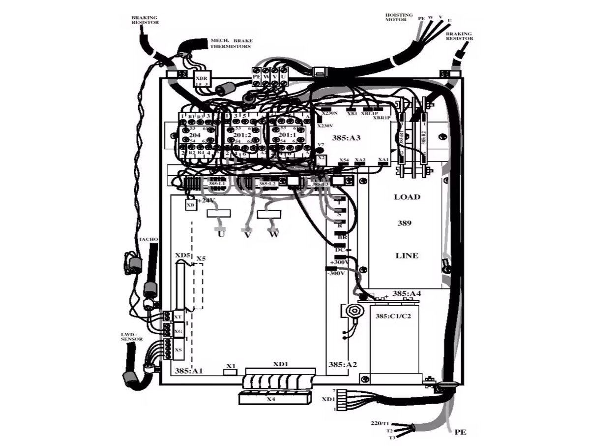
Main Components of KONE KDL16 V3F16ES
The V3F16ES drive system consists of several key circuit boards and power components.
1. A1 Drive Control Board (DCB)
Drive Control Board
The DCB is the main control unit of the inverter system.
Main functions:
- · Receives elevator control signals
- · Processes operation commands
- · Controls inverter output
- · Monitors drive operation status
It plays a central role in coordinating the entire drive system.
2. A2 Main Circuit Board (MCB)
Main Circuit Board
The MCB handles the main power circuit functions.
Main functions include:
- · Power conversion
- · Current control
- · Power switching management
- · Protection monitoring
It works together with the control board to ensure stable motor operation.
3. A3 Brake Control Board (BRK)
Brake Control Board
The brake control board manages the elevator brake-related functions.
It controls:
- · Brake release timing
- · Brake operation coordination
- · Safety-related brake control
Proper brake control is essential for elevator stopping accuracy and safety.
4. A4 Intermediate Circuit Board (IMC)
Intermediate Circuit Board
The IMC board is part of the DC intermediate circuit system.
Its functions include:
- · DC voltage management
- · Energy transfer control
- · Supporting stable inverter operation
Important Power Components
Main Contactors
The system includes:
- · 201:1
- · 201:2
- · 204 (Dynamic Braking)
These contactors control power switching and braking-related operations.
Filter System
The filter section helps:
- · Reduce electrical interference
- · Improve system stability
- · Protect electronic components
Charging Capacitors
Components:
- · 385:C1
- · 385:C2
The charging capacitors store and stabilize DC energy within the inverter circuit.
Charging Resistors
Components:
- · 385:R1
- · 385:R2
- · Resistance: 1KΩ
- · Power rating: 50W
The charging resistors limit initial charging current and protect the capacitor circuit during startup.
The KONE KDL16 V3F16ES inverter integrates multiple control boards and power components to achieve precise elevator motor control. Understanding the function of each board and circuit component is important for elevator troubleshooting, maintenance, and replacement work.
For KONE elevator parts, inverter components, and professional elevator technical support, choose YuanQi for reliable products and efficient service.
WhatsApp: 8618192988423
E-mail: yqwebsite@eastelevator.cn
Post time: Jun-30-2026